
TDA1514/TDA2040 Surround Sound Amplifier - Mark 2 - Surround Sound Amplifier Remake
Part 2 - Building
Here is where I describe a little about building the amp. All the challenges I came across and ways of getting round problems.
Width controller and decoder
The first part of the build process was to design the circuit boards. I have extensive information on how I design and build circuit boards here.
Things were quite simple for me, as I had PCB's for rear amp, centre amp and tone controls from the previous amp (and the headphone out too). This meant the only boards required was the decoder board, the front amps board, the power supply board, and a small board for mounting switches and LED's on.
As mentioned, the first board I started on was the decoder board. This was the most complex, because I tried my best to squeeze the width controller, the rear decoder and the centre decoder all on one small board. The design I came up with in actual fact was very impressive, I was quite happy.
For your information, I used the ESP stereo width controller deluxe version for both the front width controller and the rear decoder. The rear decoder uses 2 trimpots which are set in the position for maximum for maximum "split". This effectively gives me the rear speaker requirement of no centre image at all, with a bit of stereo image on the rear. The centre decoder is basically the small part from the ESP simple surround sound decoder, without the 100k potentiometer level adjustment or the 1n capacitor frequency cut-off - as I had the potentiometer later in the circuit and I prefer the centre sound not to be cut-off at high frequencies, its better sound quality to my ears. This means all the centre decoder consisted of from that project was R3, R4, R9, R10, U1B, C2 and C3. Update - I could have just used two resistors instead to make the centre channel, even easier!

You may note I didn't completely plan the layout with the size of the 1uF capacitors, and that the rear potentiometer would extend into the space for one of them. Fortunately, it could be forced in at a slight angle with no harm. It's always a good idea to wait till you have all the components before you construct the board. Overall, the board is fine though. Only a few jump wires were needed.
Once I knew where I was going, from my design, I started cutting the case up. My old amplifier had the same size heatsink as the one I planned to buy, but it wasn't reused because I couldn't face the fact it would look ugly from all the holes drilled in it. With all this information - the case was cut and the first two boards went in fine:
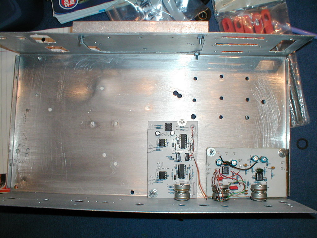
The board on the right is the tone controls, from the old amplifier. The original holes for those pots lined up fine with the boards (actually there was some extra space), so I was happy there. I came across a problem when it came to mounting the boards however. My old amplifier used a very small number of spacers, all of different heights but I wanted to do a better job. Unwilling to get ripped off by proper spacers (they were really expensive at my retailer, just for 10 of them), an idea came to mind.
![]()
Those old knackered felt tip pens! This has to be one of the cheapest ways to make spacers ever, seeing as in places you can pick up something like 50 felt tip pens for £1. They are not strong, but strong enough in the direction that matters to securely bolt down the circuit boards. The spacers are barely stressed in any way at all.
Care has to be taken when cutting them - with a hacksaw, they just snap. I used a small rotary tool (like a Dremel) to slowly ease my way through the plastic. It produced nice results and my measuring was accurate enough to have all the spacers the same height. Warning however - the plastic is very cheap, do not use it for circuitry where heat is common (not an issue with my op-amp boards), or for circuit boards with mains voltages.
PSU
My next challenge was the power supply board. The aim of this board was to provide an earth loop breaker, which is a large 10 ohm resistor, a 0.1uF 250VAC capacitor (so X-class) and two large rectifier diodes. It would also regulate the 12V transformer output to positive 12V and negative 12V for all those op-amps and provide a mounting point for large smoothing capacitors for the rest of the power supplies.
Capacitors:
Two 4,700uF 35V capacitors for my regulators, one for each polarity (+/-)
Another two 4,700uF 35V capacitors for the 18V unregulated power supply to the TDA2040 amps (rear and centre)
Two 10,000uF 35V capacitors for the 25V unregulated power supply for the TDA1514 amps (front)
Regulators:
Based on the ESP Simple pre-amp power supply, only with 12V regulators rather than 15V (7812 and 7912), and with my own 4
diode rectifier to give me the 12-0-12 AC connection a +/-18 DC output.
Earth loop breaker:
This loop breaker is based on the one in the ESP Earthing your hi-fi article.
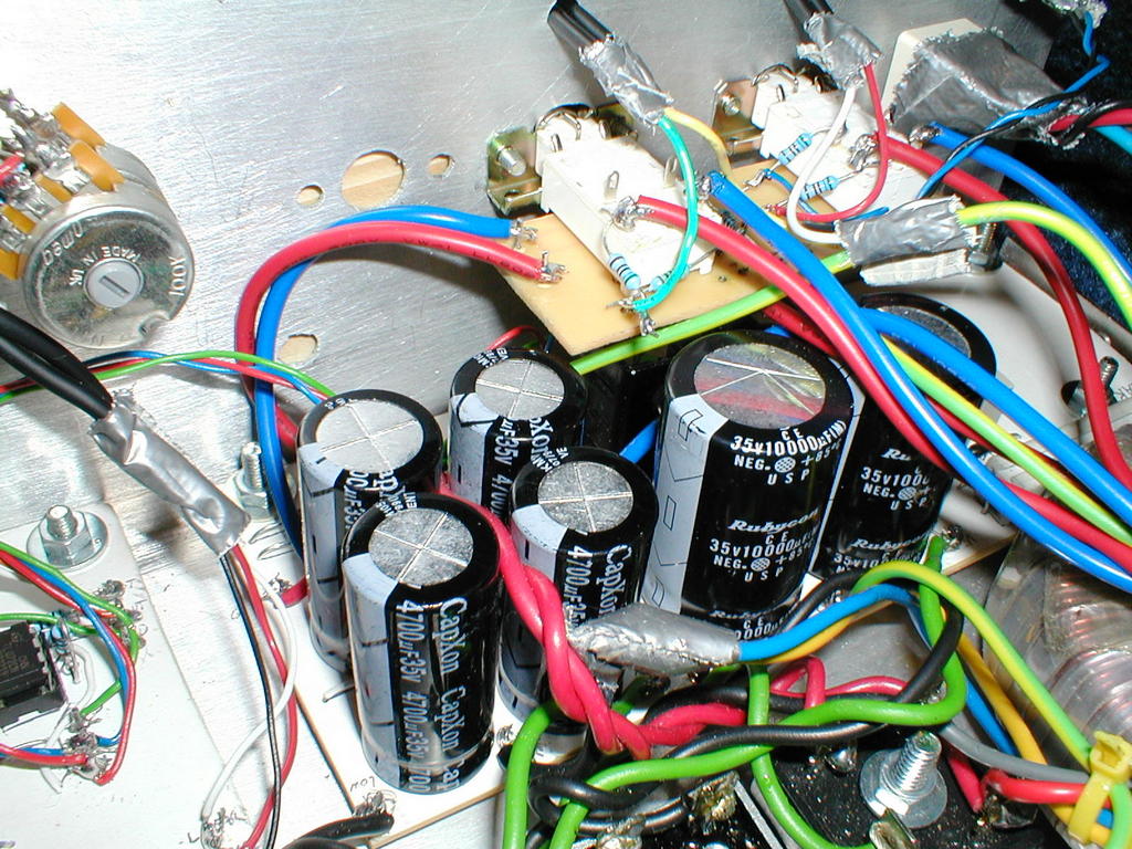
Unfortunately, I did not take a better picture of the PSU so the above is all I can show. This picture does however show the location of those huge capacitors, the regulators (not visible) are behind the two largest capacitors, and the loop breaking is on the right, and is adequately earthed to the case chassis.
Front Amplifiers
The next board to make was the all-important, all-powerful, all-great-quality TDA1514 front amplifier board. I designed this board to be able to fit both TDA1514
chips at the back of the board (for heatsink mounting) and so that the width of the board so it would be less than the total width of the heatsink with the centre
amplifier next to it. This didn't leave lots of space so my TDA1514 PCB design was a bit more cramped then my TDA2040 designs (very spaced out).
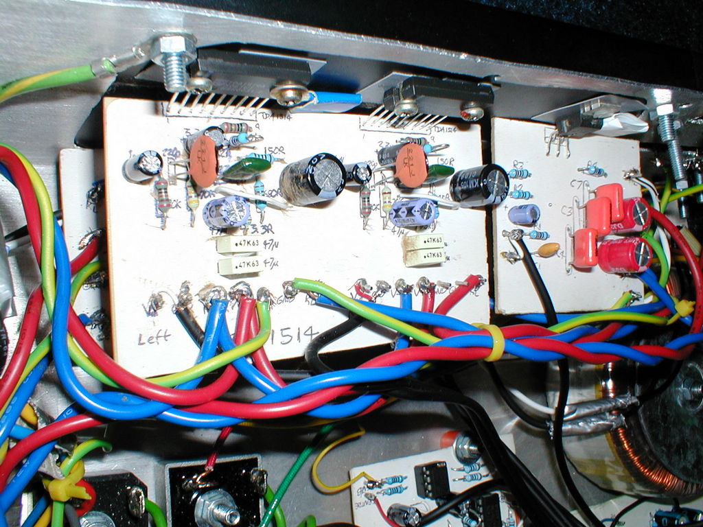
Saying that, the design was fine and the PCB traces are wide enough to carry those essential high currents to and from the TDA1514 chips themselves. A major oversight was the smoothing capacitor which jumped from the positive 25V rail to the negative 25V rail. The design was for, and initially used a 35V capacitor across here, but should have been 50V at least! After about 20 minutes that it blew up, which is why you can see some of its guts spread on the large 220uF, and on the wires. Fortunately, I could squeeze a larger 63V capacitor in its place. The board looks as below:
After the new heatsink came, I used two TO220 mica washers on each chip to provide insulation from the TDA1514 chip and the rest of the heat sink since my supplier no longer stocks the proper washers for these devices :-/ Its works though, and two screws tapped into the heatsink for each chip was enough to secure the whole assembly in place.