
TDA1015T DIY Guide - a small Surface Mount 0.5W mono amplifier
Warning: Unfortunately, this chip is now discontinued and so this article remains for reference if you do manage to get some...
In fact, it is the fact these chips are discontinued that allowed me to snatch 10 of them for a damn good price.
This article is written the night after the morning they dropped through the letter box. In that time, I have managed to create a small, in fact very small, prototype board.
TDA1015T application
Quick facts TDA1015T
- Power output: 0.5W into 16 ohms at 10% 1kHz distortion with power supply 9V
- Power output: 0.3W into 8 ohms at 10% 1kHz distortion with power supply 6V
- Power output: 0.55W into 8 ohms at 10% 1kHz distortion with power supply 7.5V
- Power output: 0.55W into 4 ohms at 10% 1kHz distortion with power supply 6V
- Gain: 29dB for the power amplifier +23dB additional gain with pre-amplifier (52dB total)
- Power supply: 3.6V to 12V single supply
- Datasheet available here
Guide
The TDA1015T is a very small surface mount audio amplifier. It was produced by Philips semiconductor capable of about 0.5W.
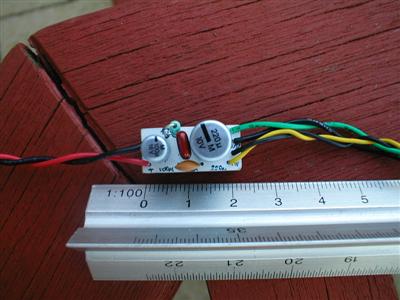
Photo showing the size of my prototype, this is not trickery, and you can see how close my camera lens was from the fish-eye effect.
The TDA1015T comprises of both a pre-amp and power amp - all in a tiny little 8-pin SO-8 (SOT96-1) package.
Gain with just the power-amp is about 29 dB, compared to 52 dB when used with its pre-amp. 52dB is an extremely high gain of 630 times - calculated as 10 ^ (56 / 20). This kind of gain is not needed for normal sources and is intended for low output sources such as tape heads, microphones etc.
Therefore, my first project only uses the power amplifier portion of the TDA1015T, which has a very reasonable gain of 29dB (28x).
At the time of writing, I do not have any plans to build a circuit that uses both the pre and power amps on this little chip...
Construction
The schematic for the power amp only of the TDA1015T amplifier, based on the application circuit from the datasheet.
Not many external components are needed to complete at full 0.5W power amplifier. This is without its pre-amp but not many more components are required to add that to the circuit too but do note the pre-amp inclusion makes the connections based in the schematic above quite different.
A volume control is included in my schematic. Whilst the datasheet does not include one and neither does my prototype, I suspect they might be useful and that's there to show you where it goes. A log type potentiometer is required and 4k7 to 10k is about right. A dual pot is needed if you plan on using two TDA1015's to complete a stereo amp.
The first thing that is important is soldering that surface mount chip. I confess, I am no expert at it, but I managed first time without any problems so I will write a few short paragraphs on my attempt.
Orientation:
Something to definitely get right. I've not known a chip of any kind that will forgive you wiring it the wrong way round. My first look at the
chip gave me a little fear. I could not tell which way it was supposed to go round as I could not see any kind of notch or circle to indicate
pin 1 at all. The only way to find out was to look at the datasheet - this clearly shows the package having a 45-degree slant on one side, and
a right angle on the other. The side with the slant denotes pins 1 to 4, 1 being at the top left corner when you have the slant on the left
hand-side (i.e., correct orientation). Once you have found pin 1, the rest is simple.
Soldering
Perhaps the most difficult part. When you think of how short those little leads are running into the tiny silicon package... heat issues are
quite scary :)
The datasheet has a few techniques into how to solder them. Read these. As for myself, I just felt comfortable enough to make sure I solder the joints very fast. First however, we must position the device ready for soldering.
I used a simple idea of using a thin strip of sticky tape (aka Sellotape). I first laid the section of tape over the device and then carefully positioned it on the board until I was happy, then stuck the whole strip down.
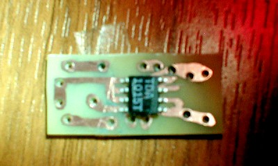
First picture, blurry, but shows how the IC pins are positioned.
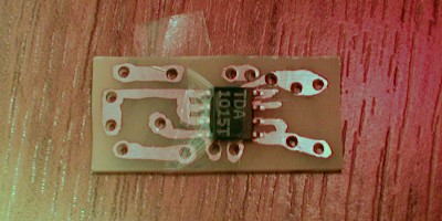
Second Picture, sharp but doesn't show the pins quite so well.
As both images show, I positioned the tape so that four of the pins can be soldered (the ones on the right). The tape held the device quite well.
As I soldered, I held the board with my finger on the chip, so I could feel if there was too much heat. I didn't feel it get hot, or even warm, once during the whole process. The basic technique I used was to get a bit of solder on the iron and place the solder over the pin and then quickly dab on a bit of solder and it very happily just flowed into place. I doubt any solder joint took me more than a second.
What I could have benefited from, and therefore recommend, though is a smaller soldering iron tip. It's on my "things to get" list now... still, I managed.
Once one side is done, leaving plenty of time between soldering each pin, remove the tape and continue onwards for the next four pins. Then the soldering is complete.
However, you still need to be extra careful with your soldering. Whilst other components will take a bit of heat, too much heat will flow along the PCB and straight into the TDA1015T. You don't really want to kill it at this stage.
The rest of the components is otherwise a simple task. Remember to pay attention to the polarity of the electrolytic type capacitors or serious injury may result.
Power
Chances are you'll want this amp portable. Batteries do the trick fine, but you won't get much power out of a couple of 1.5V cells. Unfortunately, the size of a decent amount of battery power will mean that the overall size of this amp will be much bigger and for that there are more benefits to be had using a device like the TDA7052 or TDA2822 for stereo.
For a mains supply, use a DC power adaptor. There is barely any point in having an integral mains transformer solution and DC plug blocks are far safer and easier. You will not need a regulated one, although a regulated one will work if it is all you have.
Prototype
Well, I have to say I was shocked at how small I created my prototype board. Being a surface mount device, that left me with empty space on the top of the board which was ideal to fill with parts of capacitor footprints. The total size became a very small 22mm x 10mm, beating all my previous small designs considerably.
Below are some pictures I done mostly out in natural light (for better camera results), and comments.
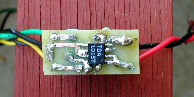
Here is a photo of the bottom of the board.
Soldering is a bit messy, but best you can do with a huge tip and tiny connections.
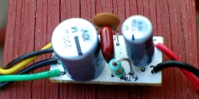
View from above.
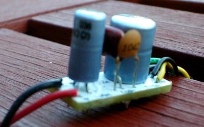
Here is a photo from above of the board.
You can see the 100nF cap (labelled 104) and the other red coloured capacitor is the 22nF one. You can also work out what electrolytic caps are
which. My resistor is 4.3R at 2%, which isn't a problem it's just I have more of these and none of the 4.7R types.
Wire colours are Yellow=Line In, Green=Speaker Out, Red=V Positive and all the blacks are grounds.
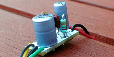
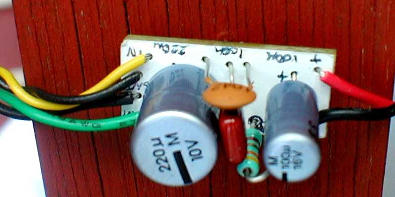
More of a side view.
Another side view, from other side.
Testing
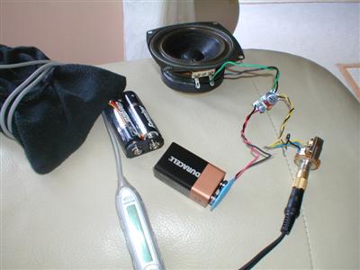
My test equipment really dwarfed the little amp. I used my MiniDisc player as a source of music and union the left and right channels at the input socket for a mono input.
My initial battery sources were two 1.5V AA cells, and to really give it a chance to perform I used my test speaker, which is a simple 8 ohm 3 inch full range driver.
After hooking up and connecting the battery box, I heard the bleep from my MD player which was the sign I wanted that all was ok. Then the music kicked in. It worked ok but didn't really give much power from that little power source. I grabbed a 9V PP3 battery and used that to see if it could get a bit more volume. The performance increase was greater, and enough to produce quite a bit of cone excursion on my loudspeaker. Note that a PP3 battery is not a good power source for amplifiers and will drain fast.
9V is pushing the amplifier harder than it's intended to into 8 ohms though. You should keep to within 7.5V to prevent overheating. Into 4 ohms, do not exceed 6V. If you have 16 ohm speakers, then it's OK to push the voltage up to 9V to hit 0.5W. 12V is only intended for using with 32 ohm speakers.
The device is only 0.5W however and nothing loud can really come from this amp, it just does surprisingly well from the tiny size of it.
As the TDA1015T is a single ended amplifier, it would be possible to bridge to allow two of them to push nearly 2W into 8 ohms on 6V. Unfortunately bridging is not easy as there is no inverting input pin to tap into so you would need to have a bridging adaptor based on either a dual op-amp or audio transformers. Once you factor these in, the cost/size does not outperform dedicated BTL amplifier chips.